Electricity is present (in some form) in every laboratory on campus and presents unique risks relative to other hazards. The invisible nature of electrical current makes locating and assessing hazards difficult, but with some guidance and implementation of good work practices, risk of injury and/or damage from electricity can be greatly reduced.
Terminology
There are many different terms used by engineering, electricians, and hobbyists to describe all of the aspects of electrical energy. The common terms used on our website and in our trainings are defined below:
Voltage (V): Difference in electrical potential energy between two conductors. Measured in Volts. Also referred to as potential.
Overvoltage: a voltage greater in magnitude than the nominal rating of a circuit.
Current (I): Magnitude of electrical charge flowing through a conductor. Measured in Amperes.
Overcurrent: Any current above the nominal rating of a circuit or piece of equipment.
Current Draw (link): Current required for the normal function of electrical equipment.
Power (P): Electrical energy transferred through a circuit per unit time. Measured in Watts.
Power Relation: P [Watts] = I2 [Amps] × R [Ohms] = I [Amps] × V [Volts]
Impedance: Opposition to current flow in a circuit. Most common form is resistance (R); measured in Ohms [Ω].
Alternating Current (AC): Voltage oscillates at a set frequency and current flows in two directions. Voltage is reported as root-mean-square (RMS) of voltage amplitude.
Direct Current (DC): Voltage is constant and current flows in one direction.
Conductors: Materials that have little electrical resistance; current flows easily through conductors.
Insulators: Materials that have high electrical resistance; current does not flow easily through insulators. Insulators can also be referred to as dielectrics.
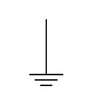
Ground: A conductive connection to Earth which serves as a sink for current. Serves as a reference point for zero volts; voltages are measured with reference to the ground. The symbol used for ground in circuit diagrams is denoted with three parallel lines of decreasing size; see below:

Grounding: Establishing a conductive channel between a circuit, panel, or piece of equipment and Earth.
Short: An electrical connection, often unintentional, which results in unintended current flow with very little (or less than nominal) resistance.
Short Circuit: A failure of a circuit resulting from a short. This term is often (incorrectly) used to describe any electrical issue in a piece of equipment.
Receptacle: The technical name for a wall outlet. The terms outlet and receptacle are used interchangeably on this page and in other DRS materials.
Arc: A plasma with a high energy density that is the result of electrical breakdown of a gas caused by a sufficient electric field between two conductors.
Wall Power and You
Understanding how electricity flows through a wall receptacle (outlet) can be important for working safely in the laboratory. The following diagram illustrates the functions of the different plugs on a common wall receptacle.
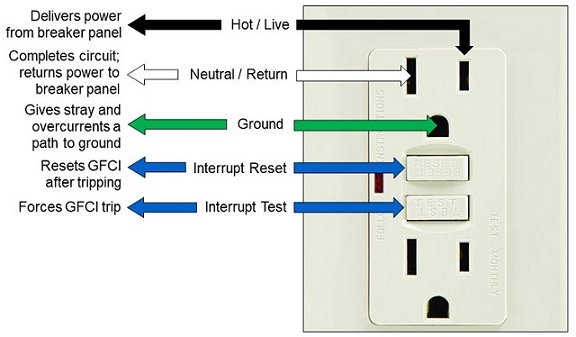
This diagram shows the importance of plugging in equipment the right way. Do not force a plug into an outlet; this could reverse the hot and neutral connections and result in the equipment (or you) being damaged. Also, connections should not be altered on cords or equipment in an effort to use a wall receptacle outside of specification.
Electrical receptacles come in many shapes and sizes and are used for varying purposes, depending on the voltage and current specifications of the circuit/equipment. For example, medium to large size air conditioners generally cannot be plugged into a standard receptacle because they draw more current than what a typical receptacle can provide. Some examples of these types of plugs and outlets are shown below:
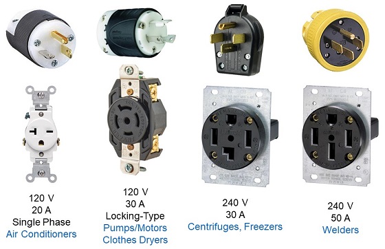
Be sure that you are using the proper plug/receptacle combination to provide power to your equipment. Never force a plug into an outlet.
Electrical Hazards
Shock Hazards
Electrical shock occurs when current passes over or through the body as it travels to a lower potential, usually (but not necessarily) to ground. The severity of a shock depends on the magnitude of the current to which the victim is exposed, the time the victim is exposed to that current, and which part of the body has become a part of the circuit. Shocks can be harmless to fatal across a range of only a few Amperes; a person can easily be electrocuted (fatally shocked) by appliances in their homes.
At some point, you may have heard or seen the phrase “the current is what kills you.” This refers to the fact that the energy flowing through a circuit is represented by the current. High voltage can be harmless, in some cases, if the current is negligible. The voltage will, however, dictate the magnitude of the current at a given resistance according to Ohm’s Law:
V (Volts) = I (Amps) × R (Ohms)
Depending on the severity of a shock, a victim can suffer superficial burns, deep (muscular) burns, “reflex” injury (from reflex response to pain), respiratory and/or cardiac arrest, and/or death. The table below summarizes the physiological response to electrical shock that a victim will experience depending on the current to which they are exposed:
Current (Amps) | Physiological Effect(s) |
0.001 | A slight tingle is felt; generally harmless. |
0.005 | Slight shock felt. Disturbing, but not painful. Most people can "let go." Strong involuntary (reflex) movements can cause injuries. |
0.006 - 0.025 (Women) | Painful shock felt. Muscular control is lost. "Freezing” currents become more likely; it may not be possible to "let go." |
0.050 - 0.150 | Extremely painful shock felt. Respiratory arrest and severe muscle contractions likely. Muscle response could “freeze” body to circuit. Heart fibrillation possible. Death is possible. |
1.0 - 4.3 | Cardiac disruption likely. Strong muscular contraction and nerve damage occur; death likely. |
≥ 10 | Cardiac arrest and severe burns occur. Death is probable. |
15 | Lowest overcurrent protection for standard wall outlets. |
Source: Kouwenhoven, W.B. [1968]. Human Safety and Electrical Shock. Electrical Safety Practices, Monograph 112, Instrument Society of America, P. 93.
The “let go” threshold is mentioned in the table above and is an additional consideration when working with electrical circuits. In North America, wall outlets produce power at a frequency of 60 cycles per second (60 Hz). At this frequency, electrical current interacts with the body in such a way that causes involuntary contraction of the muscles. When this happens, the muscles of the hand can contract, which could result in a victim gripping a live conductor more tightly. The victim may be unable to “let go” of the conductor until it is de-energized; power will have to be shut off at a breaker panel to rescue a victim frozen to a circuit.
Fire Hazards
Overheating
Current flowing through a wire generates heat. Cords are engineered to allow for some heat dissipation, however, current in excess of the rating of a wire will cause the wire and its insulation to overheat and smolder, which could lead to a fire.
This overheating of conductors and cords is one of the most common causes of fires on campus. To avoid fires as a result of overheating, implement the following:
- Avoid the use of extension cords if at all possible.
- If using an extension cord, ensure that the proper gauge cord is used (see Wire Gauge).
- Do not connect extension cords in series. In other words, do not connect multiple extension cords to make a longer extension cord. This will increase the resistance of the cord, which will in turn increase the current flowing through the cord.
- Inspect flexible cords (extension cords and equipment cords) on a regular basis. If cords appear damaged, replace the cord or piece of equipment immediately.
- Do not run flexible cords through walls, doors, hallways, windows, under carpeting, or drape them across light fixtures.
- Do not overload surge protectors. Ensure surge protectors are rated for the current to which they are subjected (see Current Draw).
- Ensure that the appropriate insulation is used for electrical conductors.
- If you design or build electrical equipment or circuits, consider installing fans and/or heatsinks for temperature management.
Ignition of Vapors by Sparks and Static Discharges
Sparks generated by electrical equipment and electrostatic discharges (ESDs; think socks on a carpeted floor) can ignite flammable gases and/or vapors. This was, for example, determined to be the cause of a compressed gas cylinder explosion which severely injured a researcher in 2016.
To minimize the risk of ignition of flammable vapors by sparks, do the following:
- Avoid using equipment that is excessively old or appears to be in poor quality. If you notice an electrical failure, immediately de-energize and remove the failing equipment.
- Avoid using electrical equipment in close proximity to flammable materials. This is particularly important around volatile solvents, flammable materials, and inside of chemical fume hoods.
- Do not store flammable materials in standard use refrigerators. Only refrigerators designed and certified by the manufacturer to store flammable materials shall be used. Modifying standard use refrigerators in any fashion is strictly prohibited. Previously modified refrigerators may not be used.
- Avoid using high concentrations of flammable gases if possible. AirGas offers a variety of flammable gases in dilute concentrations (5% H2 in Ar, for example) as alternatives.
- Ensure that you are not storing a larger volume of flammable liquids than what the square footage of the lab space dictates. Contact DRS if you are unsure about the maximum allowable quantity of flammable materials allowed in your lab space.
- Ensure that flammable materials and gases are used and stored properly, and that flammable vapors are not present in large concentrations near electrical equipment.
- If using electrical equipment in a high-hazard operation, utilize explosion-proof or explosion-rated equipment. Explosion-rated electrical components should be installed by a University-approved electrician.
- Solvent drums > 4 L in volume should be grounded or bonded to a grounded conductor. (See Grounding and Bonding)
Discharging Static Electricity
While not an issue of personal safety, if you are working with sensitive electronics, it is in your best interest to minimize the risk of ESDs. ESDs can become particularly problematic during the dry Illinois winters, so take extra care as the air gets less humid. Harmful ESDs can be avoided in some of the following ways:
- Ground yourself before going near any circuit components. Touch a large metal object (equipment panel, computer casing, etc.) to discharge any charge stored on your body.
- Use a grounding strap to keep yourself grounded while you are working. Many varieties are available from various retailers.
- Work on a non-conductive surface such as a rubber mat. This applies to the benchtop and the floor.
General Electrical Safety
The following are general recommendations for working with electrical equipment in the laboratory:
- Unplug and/or de-energize equipment before running diagnostics or performing maintenance whenever possible.
- Use electrical equipment only if it is in good condition. Cords must not be cracked, frayed, or have corroded prongs. Receptacles should have covers in place and should not be damaged or corroded.
- Do not use 3-to-2 prong adapters. Plug 3-prong plugs into 3-prong outlets.
- Do not link surge protectors or power strips/taps in series (daisy chaining).
- Do not leave cables and cords unsecured and/or hanging in areas where they can pose a trip or movement hazard.
- Do not subject cords to mechanical stress or temperatures that could damage the insulation.
- Do not use electrical cords to support weight of any kind.
- Avoid placing electrical cords, especially live plugs, receptacles, or connections, on the floor. In the event of a flood, the flood water can become energized. Elevate cords using conduit or raceways where possible. At a minimum, use a highly-visible cable protector to avoid trip hazards.
- Do not conceal cords behind or attach electrical cords to building surfaces. Do not run cords through holes in the wall or through doors or windows.
- Do not leave electrical circuits exposed. Use electrical tape to insulate wires or use a guard as a cover to prevent accidental contact.
- Do not block access to electrical panels. Allow three feet of unobstructed clearance in front of breaker panels and switch boxes.
- Do not install standard electrical equipment in locations where flammable gases, vapors, dusts, or other easily ignitable materials are present.
- If equipment is used in a chemical fume hood, elevate the equipment to allow for sufficient air flow under the equipment and through the fume hood.
- Do not place surge protectors inside of a chemical fume hood.
- Keep electrical equipment to a minimum in high-moisture areas.
- When turning equipment off, allow several seconds for the equipment to fully discharge any stored energy before unplugging. A ten-second rule is generally acceptable.
Here are some recommended practices to employ to keep you safe when working with electricity:
- Wear appropriate PPE (see PPE section).
- Avoid wearing rings, watches, bracelets, necklaces, or other electrically conductive jewelry.
- Avoid being grounded when near live equipment—this is an easy way to become part of a circuit and receive a shock. Stay at least 6 inches away from large pieces of metal, walls, and water sources (pipes and standing water) when working. Wear shoes with thick, insulating soles or use non-conductive mats.
- Use the one-hand technique. Work with only one hand, and place the other hand at your side, in a pocket, or in a belt loop away from conducting materials. This will ensure that, in the event of an accidental shock, the current does not pass across your heart.
- Use tools designed for electrical work that have a non-conductive cover or casing. Electrically insulated gloves are also available.
Electrical Equipment
Extension Cords:
Extension cords are not a suitable replacement for permanent wiring. Receptacles should be installed in areas where electrical power is needed permanently. Discuss your need for receptacles with facilities staff.
Extension cords should not run through holes in walls, ceilings, or floors; nor through doorways or windows. Cords should be inspected before each use.
Extension cords should not be used in series. Do not plug one extension cord into another extension cord. This extra connection can affect the total resistance of the cord, which could in turn result in overheating of the cord and melting of the insulation. Either use a single cord of a longer length, or find a different receptacle to power the equipment.
Wire Gauge:
The thickness of a conductor is proportional to the magnitude of the current it can withstand without overheating. The thickness of conductors (in North America) is measured using the American Wire Gauge (AWG) system. Generally, the smaller the AWG value, the larger the diameter of the conductor and the larger current the conductor can carry. One must consider using the appropriate gauge wire when using flexible or extension cords and when designing circuits.
Cords come in various conductor sizes, and the required gauge is determined by the power of the equipment which is plugged in. Cords have current/power ratings; ensure that the cord you are using is rated for the current/power of your equipment. This value is usually printed on the insulation of the wire, along with the voltage, temperature range, and usage codes. Flexible cords must be rated for hard or extra-hard usage (S, ST, SO, STO). A listing of usage codes for flexible cords and cables can be found in Articles 200 and 400 of the National Electric Code (NEC).
The table below lists the National Electric Code recommended gauge of electrical cords as a function of length and current draw:
| Cord Length (Feet) | |||
Current (Amps) | 25 | 50 | 100 | 150 |
0-6 | 18 AWG | 16 AWG | 16 AWG | 14 AWG |
18 AWG | 16 AWG | 14 AWG | 12 AWG | |
10-12 | 16 AWG | 16 AWG | 14 AWG | 12 AWG |
12-16 | 14 AWG | 12 AWG | Not Recommended | |
Surge Protectors:
Surge protectors are a great way to provide power to multiple (low current) pieces of equipment. However, there are some considerations regarding surge protectors:
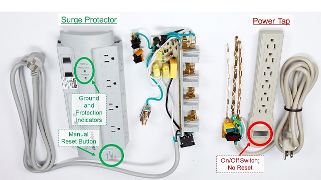
1. A surge protector is different than a power strip/tap. A power strip/tap only makes more connections to a circuit and provides no overvoltage protection. A surge protector, on the other hand, has an internal fuse or circuit breaker that will trip in the event of a rapid power fluctuation, preventing damage to equipment resulting from a power surge. A power strip/tap cannot adequately protect sensitive equipment from the temporary high voltages caused during power surges.
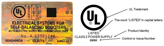
2. Use a UL-listed surge protector. A certified piece of equipment will have a UL label (rainbow foil). Within the past several years, increasing numbers of fraudulent UL labels have been seen on electrical equipment: be careful about what you purchase. Something that looks like a cheap option could in fact be quite unsafe. This does not apply to just surge protectors—all commercial equipment used in the laboratory should be UL-listed. Look for the labels on your equipment:
3. Do not overload surge protectors. This increases the risk of electrical fires dramatically. (See Current Draw)
4. Some types of electrical equipment are not meant to be plugged into a surge protector. Equipment with a moderate to high current draw (heating elements, motors, air conditioners, power supplies, etc.) should be plugged directly into a wall receptacle, rather than into an extension cord or surge protector.
5. Refrigerators should not be plugged into surge protectors for the same reason given in 4. Refrigerators draw a significant amount of current, especially in warm weather. Furthermore, a surge protector/power strip may require a manual reset after a surge. An un-noticed trip could result in the contents of a refrigerator unknowingly coming to room temperature, which could be a tremendous financial and emotional/logistical loss for a research project.
6. Sparks can also be generated within a surge protector, which could easily ignite flammable vapors. For this reason, surge protectors should not be placed inside of chemical fume hoods.
Current Draw:
A surge protector does not guarantee safety when using electrical equipment. This is particularly important regarding the total current draw of equipment which is plugged into a circuit. Typical wall receptacles are rated for 15 Amps; any value greater than 15 Amps will likely result in overheating of conductors or continued tripping of the circuit in question. If this is happening, be sure to plug your equipment into multiple circuits. If the problem persists, have your equipment or laboratory wiring evaluated.
Important: Using a different outlet does not necessarily mean you are using a different circuit. If the new outlet is on the same circuit, the circuit will still “feel” the same current draw, and tripping of the circuit is still likely.
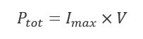
The total current draw of the equipment being used can easily be calculated; this value will determine whether the circuit in question will be overloaded. We can re-write the power relation (P = IV) to say that the total power (Ptot) is equal to the maximum current (Imax) times the voltage of the circuit.
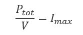
We can then solve for the maximum current:
Using the equation given above, consider the following examples:
- A surge protector into which is plugged:
- 2 1000 W heaters
- 1 500 W microwave
- 2 60 W light bulbs
- 1 1000 W power supply
First, we determine the total power by adding the power ratings of the individual pieces of equipment. We then divide the total power by 120 V (standard wall voltage).
The maximum current is therefore: 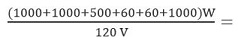 30 Amps.
This is twice the current rating of a normal wall receptacle, and would likely melt the surge protector in a matter of several seconds.
Now, consider the following:
- A single receptacle into which is plugged:
- 1 1000 W heater
- 1 500 W power supply
Similar to Example 1, we calculate the total power and divide by the voltage.
The maximum current in this example is therefore 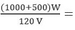 12.5 Amps.
Although this is a fairly large current, this is well within the operating limits of a typical wall receptacle.
Ground Fault Circuit Interrupters (GFCIs):
A ground fault circuit interrupter (GFCI) is a protective device installed on an electrical circuit which quickly opens the circuit (stopping current flow) if an overcurrent is detected.
GFCIs are required to be installed on circuits that are within 6 feet of a water source. In the event of a splash, rather than receiving a shock, the researcher will be protected by the GFCI. If you do not have GFCI protection installed on circuits near water sources in your laboratory, contact the facilities personnel in your building/unit to discuss installation of GFCIs.
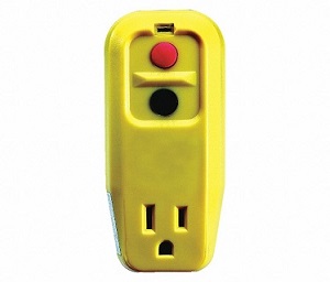
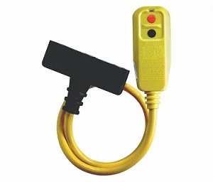
Avoid plugging equipment into any circuit without GFCI protection, if possible. Avoid using non-GFCI protected outlets near water sources. Certified, portable GFCIs are available for purchase if no GFCI wall outlet is present. If working in a wet area that is normally dry, a portable GFCI should be used. The following images are examples of acceptable portable GFCI units:
GFCIs should be tested on a regular basis, either with a GFCI testing device or by using the test/reset buttons on the outlet.
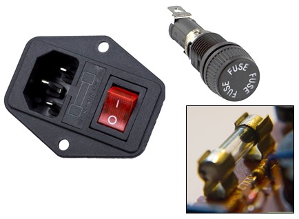
Fuses:
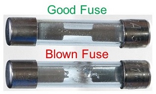
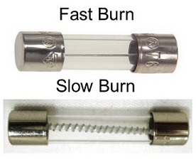
Fuses are another example of safety devices that protect equipment from overcurrents. Fuses are found in most commercial equipment, and come in several varieties. When too much current flows through a fuse, the conductor inside the fuse melts, permanently disconnecting the circuit. The melting of this wire is commonly referred to as “blowing a fuse.” Below is a comparison of a functional fuse versus a blown fuse:
Fuses can be found in various locations in electrical equipment. On the outside of the equipment case, fuses are usually positioned near the power input. Fuses can also be located on the surface of circuit boards. Some example images are included below to show where fuses might be located on electrical equipment.
There are different varieties of fuses rated for different voltages and currents, but there are additional considerations, including the ‘burn time’ of the fuse. A fast burn fuse will blow in a matter of a few milliseconds, and slow burn fuses can burn considerably longer. The main difference between the two types of fuses is the magnitude of current that the fuse can withstand. Slow burn fuses generally have a larger “I2·t” value, which means that they can withstand stronger current transients than fast burn fuses of the same current rating.
When choosing replacement fuses, use only those specified by the equipment manufacturer. Never replace blown fuses with fuses of different ratings; this could cause hazardous and/or damaging overcurrents in your equipment or result in equipment not functioning properly.
Never insert in-line fuses into a live circuit. Always disconnect the circuit or unplug equipment before inserting an in-line fuse. If the new fuse blows again, have the equipment checked by a campus shop, electrician, or the manufacturer—there must be a reason that this problem is occurring.
Multimeters:
Multimeters are designed to operate safely up to a certain voltage. Multimeters can explode in your hand if subjected to voltages outside of their specification. There are, therefore, different types of multimeters rated for different voltages. Typically, low-end meters are safe to use up to 600 Volts. More robust multimeters which are safe to 1000 Volts are also available, but their price point increases significantly. There are also clamp-type meters which can be used in high-current applications; these units function as non-contact testers.
Furthermore, the test probes used with multimeters are also different depending on the application. Larger probes or probes with shorter metal connections are available, for example. Choose the meter and probe combination that is appropriate for your application.

Stored Electrical Energy
One of the most hazardous operations involving electricity is the use of stored electrical energy. The two types of electrical energy storage circuitry considered here are capacitors and batteries. In addition to the same hazards as described above (shock, thermal, etc.), other hazards are present when electrical energy is stored.
Most varieties of battery rely on a chemical process to generate current, and in these reactions, hydrogen gas is a common byproduct. Hydrogen gas is flammable and can cause an explosion if the concentration in air becomes sufficient. Areas in which batteries are used should be well-ventilated for this reason. This is the reason, for example, that most car batteries have a gas vent to allow the safe release of hydrogen.
The electrolytes within many batteries can be toxic or corrosive; engineering controls should be used and proper PPE worn when working with electrolytes. A breached (leaking) battery is hazardous and should be submitted as chemical waste to DRS.
Lithium ion and lithium polymer (LiPo) batteries are en vogue for research applications. The incidence of lithium ion and LiPo battery fires have increased dramatically over the past decade, both in the general population and on the UIUC campus.
For additional information regarding battery safety, refer to our Battery Safety page.
Capacitors:
Capacitors, especially high-voltage capacitors, are one of the most deadly pieces of electrical research equipment. What makes capacitors inherently hazardous is how quickly they discharge their energy, and that high-voltage capacitors used in the laboratory generally do not have any overcurrent protection. This means that incredibly large currents can be discharged over milliseconds from a capacitor, which could also result in an arc flash event.
Accidental contact with a charged capacitor can result in a victim being subjected to an impulse shock as the capacitor discharges. In addition to the shock, thermal, and arc hazards, impulse shocks usually result in a large involuntary contraction of muscles (reflex action).
Working with capacitors or capacitor banks requires a few additional considerations:
- Type of capacitor. Some capacitors are oil-filled, and this oil may contain polychlorinated biphenyls (PCBs), which are highly toxic. Before beginning work with a capacitor, know what your electrolyte is.
- Capacitors should be shorted when not in use to avoid unwanted charging. A relatively thin gauge wire can be used to short the capacitor terminals.
- The ground connection between the capacitor and Earth should have some amount of resistance (hard grounding). With no resistance, a capacitor will discharge almost instantaneously, and this could result in harmful transients being produced in a building’s distribution system and/or an arc flash. A few kiloOhms of high-power resistance (i.e., ceramic power/ballast resistors) can be used to avoid these dangerous impulse currents.
- Grounding and discharge sticks should be available and connected to a secure and robust Earth ground when using capacitors.
- Grounding sticks (negligible resistance) should be used to short a high-voltage connection to ground.
- Discharge sticks (some resistance) should be used in stored energy applications. The added resistance “slows down” the impulse current leaving the equipment to avoid an arc flash.
- A complete grounding system for robust DC systems includes both a grounding stick and a discharge stick.
- NEVER assume a capacitor is discharged, even if you were the last person to do so. Keep this assumption in mind when drafting SOPs and when working in the laboratory.
Even 10 Joules of stored energy can be extremely dangerous. In 1996, a graduate student researcher came in contact with a 10 J capacitor which was part of a commercial microwave oven and suffered an impulse shock [Gordon, 1991]. The shock did not stop the victim’s heart, but they were unconscious for several hours. In addition to some burns on their skin, the victim’s body jerked so violently that they also dislocated both shoulders as a result of the reflex response. One dislocation was severe enough that surgery was required.
Good Work Practices
Labeling Electrically Hazardous Equipment/Experiments
Electrical hazards are essentially invisible unless they are labeled, which can be extremely dangerous. It is therefore recommended that hazardous electrical equipment and circuits should be labeled as such.
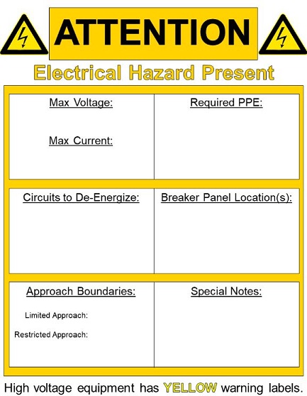
For laboratories with electrical hazards, it is recommended that the presence of electrical hazards be posted outside the laboratory space. This will both inform people entering the space to be aware of electrical hazards and will assist rescuers and electricians in de-energizing equipment in the event of an emergency. The maximum voltage and current of equipment in the space, required electrical PPE, locations and (numbered) circuits of hazardous equipment should be included on this label. See the example below:
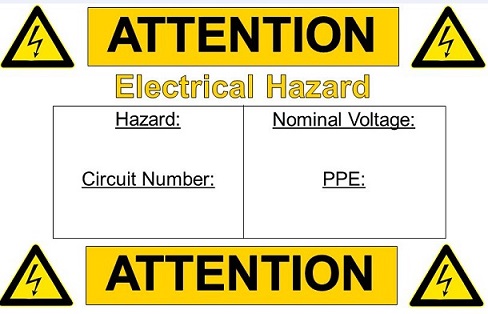
Furthermore, equipment or areas within the lab should be noted as electrically hazardous to raise awareness and prevent accidental contact with live equipment. A smaller version of the label shown above can be used for this purpose. This label is easy to see from a distance and also specifies the parameters of the equipment/circuit in question:
DRS has blank templates of these signs that you are welcome to complete and post in your laboratories.
Standard Operating Procedures for Electrical Hazards
Experiments that involve any sort of hazard should be documented with some form of a standard operating procedure (SOP). This is no different for hazardous electrical equipment or circuits. However, SOPs for electrical hazards must document information not normally included in other SOPs.
When writing an SOP for electrical hazards, the following details must be included:
- A (simplified) single-line diagram detailing the major components of the circuit.
- Voltage / Frequency / Current / Power / Energy used.
- What circuits are involved, i.e., what numbered circuits at the breaker box?
- Should any circuit components be locked out when they are not in use?
- Is everything shielded, guarded, and grounded appropriately?
- What hazard classification applies to this procedure or equipment?
- Is PPE necessary for this application?
- Have personnel been trained for this application?
DRS has an SOP template for electrically hazardous procedure that you are free to use. Please contact DRS with any questions related to completing an SOP for electrical hazards.
Bonding and Grounding
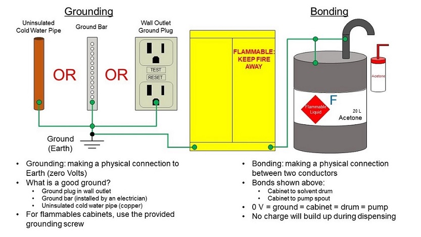
Flammable solvent containers (greater than 4 liters in volume) must be grounded to a reliable, i.e. conductive, Earth ground, whether directly or by being bonded to a grounded conductor. Keep in mind that simply placing a container on a floor does not ground it, as most floors are not conductive and not necessarily connected via a conductor to the ground outside.
As liquid flows from a vessel or through piping, charge can build up on the surface of the vessel or pipe. If enough charge accumulates, a spark (which can ignite flammable vapors) can occur between the containers. Grounding the containers will prevent charge buildup from the flow of the liquid between the containers and prevent sparks from occurring.
The figure below is a general suggestion for establishing a secure electrical ground. Electrical connections are illustrated with green lines, and closed circles indicate a connected circuit. In campus buildings, cold water pipes and ground plugs in wall receptacles are the two simplest ways to access Earth ground.
To ground a conductor to a cold water pipe, a wire can be clamped to the pipe. Note that for pipes, the wire must touch bare copper; painted, powder coated, or insulated surfaces will not work as a functional ground. Bare metal must touch bare metal for current to be able to flow.
Another option is to install a conductive bar that has a direct connection to Earth ground; this is commonly referred to as a ground bar or ground bus. Consult an electrician or your facility manager to ensure this is done properly. This option is a better choice for applications which require many ground connections, for instruments which are electronically sensitive to noise, and high voltage, high current, or stored energy applications. The recommended method of connecting a wire to a ground bar is to use a ring terminal in conjunction with a nut, bolt, and washer. Clamp-type bonding wires may be clamped to the ground bar, provided the clamp has sufficient strength to stay attached to the bar.
Bonding, on the other hand, is physically connecting two pieces of metal with something conductive. This will ensure that the two pieces of metal are at the same potential (voltage). If one properly bonds a container to something which is grounded (a grounded flammables cabinet, for example) then the container is also grounded.
Remember, just because two things are bonded does not mean that they are grounded. If you have questions about grounding and bonding in your application, contact DRS.
Electrical Personal Protective Equipment (PPE)
The PI, through the development of SOPs, determines what personal protective equipment (PPE) is required to protect laboratory personnel from the hazards to which they are exposed. DRS can assist with PPE selection.
Closed-toed shoes and clothing that completely cover the legs are necessary when in the laboratory. When working near or with electrical hazards, shoes with non-conductive soles (thick rubber or leather) should be worn.
Eye Protection. Safety glasses should be worn at all times when in the laboratory. Safety glasses and eyewear must be ANSI Z87.1 certified to offer all of the desired protective qualities. This certification, however, is not the only thing to consider; additional protections should be considered (i.e., chemical, laser, etc.) if additional hazards are present.
Gloves. Whenever rubber-insulated protective gloves are required for shock protection, approved protective (leather) gloves must also be worn. The leather gloves must be worn on top of the dielectric gloves.
Grounding and Discharge Sticks. Equipment designed for the safe discharge of stored energy should be present and available in the event of interlock or system failure. A grounding stick should be rated for the voltage and current that would be expected during a fault. A discharge stick should, at a minimum, be rated for the same values, but impulse currents in the event of a fault should be known. This is especially important for stored energy in DC systems. A robust, secure, and frequently-checked ground connection should be used with grounding/discharge sticks.
Clothing. Personnel should wear appropriate AR clothing and PPE whenever there is potential exposure to an electrical arc flash. An incident energy analysis will dictate the required Arc Rating (AR) or Arc Thermal Protection Value (ATPV) for PPE. AR clothing must meet the requirements of ASTM F1506-18.
Additional PPE. In addition to those types of PPE described above, other PPE does exist and can be appropriate based on hazards.
- Hardhats (ANSI/ISEA Z89.1)
For more information, refer to the DRS guidance document Personal Protective Equipment.
Lockout-Tagout (LOTO) Procedures:
Control of Hazardous Energy Program (LOTO) is a technique used to prevent injury or equipment damage when performing maintenance on a system. The idea is to de-energize the power source and physically lock the mechanism that will turn the power back on so that work can be completed safely. This is particularly important for procedures or equipment which involve multiple rooms and/or personnel.
For training on LOTO, contact Safety and Compliance at safetyandcompliance@illinois.edu.
Links and references
Training- Electrical Safety Fundamentals; Risk Assessment, Recommended Practices.
The guidelines and recommendations found in this program are primarily based on the following sets of regulations:
- NFPA 1
- NFPA 70 (NEC)
- NFPA 70E
- NFPA 77
- CFR 1910 Subpart S: Electrical
- CFR 1910 Subpart R .269: Electric Power Generation, Transmission, and Distribution
- CFR 1910 Subpart I .137: Electrical Protective Equipment
In addition to the regulatory bodies used within this program, components of safety programs from the following institutions were also utilized:
- Department of Energy Integrated Safety Management Policy
- Department of Energy Electrical Safety Handbook (2013)
- Lawrence Berkeley National Laboratory Electrical Safety Manual
The following publications were used in various places on this page:
- NRC (National Research Council). Prudent Practices in the Laboratory. Handling and Management of Chemical Hazards. National Academy Press: Washington, DC, 2011.
- L. B. Gordon and L. Cartelli, "A Complete Electrical Hazard Classification System and its Application," 2009 IEEE IAS Electrical Safety Workshop, St. Louis, MO, 2009, 1-12. DOI: 10.1109/ESW.2009.4813972
- C. F. Dalaziel, “A Study of the Hazards of Impulse Currents,” Trans. AIEE Part III: Power Apparatus and Systems, 72(5), 1953, 1032-1043. DOI: 10.1109/AIEEPAS.1953.4498738
- L. B. Gordon, “Electrical Hazards in the High Energy Laboratory,” IEEE Trans. Ed., 34(3), 1991, 231-242. DOI: 10.1109/13.85081
- Krieger, G. R.; Montgomery, J. F. Accident Prevention Manual, 11th ed.; National Safety Council: Itasca, IL, 1997.
The following are non-authoritative but helpful references based on the OSHA and NFPA rules as well as the experiences of practitioners:
- C. R. Miller, D. Sandefur; Illustrated Guide to the National Electric Code, 9th Ed.; Cengage: Boston, MA, 2024.
- D. K. Neitzel,; M. Capelli-Schellpfeffer, A. Winfield; Electrical Safety Handbook ,5th Ed.; McGraw Hill, New York, NY, 2019.
- F. R. Spellman; How To Survive an OSHA Audit (Spellman), 2nd Ed.; CRC Press, Boca Raton, FL, 2021.
- J. R. White; Electrical Safety – A Practical Guide to OSHA and NFPA 70E, 2024 Edition; American Technical Publishers, 2024.